 Range Rover P38 Electronic Air Suspension
 OK. I admit it. After two and a half years of messing about with the Air
Suspension on my 1996 Range Rover 4.6 HSE I had had a serious sense of humour
failure. I can't complain about the main agent as they had long since
ceased to charge me for the work on the EAS but even plaintive phone calls from
them to the factory was just resulting in bits being changed and no fix that
lasted.
OK. I admit it. After two and a half years of messing about with the Air
Suspension on my 1996 Range Rover 4.6 HSE I had had a serious sense of humour
failure. I can't complain about the main agent as they had long since
ceased to charge me for the work on the EAS but even plaintive phone calls from
them to the factory was just resulting in bits being changed and no fix that
lasted.
So what was happening? I would drive for a while with all the abilities to
change the ride height you would expect from a car that promises serious
off-road abilities and was over £60K when new but after a while all the
lights on the suspension controls would come on and adjustment would be no
longer available. Then, some times a few weeks later, some times just a few
miles, the computer would totally loose the plot, open the dump valves and drop
me onto the bump stops and display the dreaded SLOW:35 MPH
MAX message.
After a couple of limp homes like this, one from Derby to Brighton, and then
discovering that when the main dealer plugged in his Test Book and reset
things it all worked well again with no sensible reported error I started to
get annoyed.
 I purchased a kit on EBay to fit T-connectors into the air suspension lines so
you could blow them up manually. Now I suspect that when people are selling
kits to fix a fault the problem is widespread so I am more surprised there
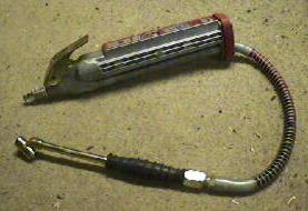
wasn't a factory fix. Anyhow with the kit fitted, a handy scuba cylinder of
compressed air in the boot and a scuba drysuit feed stuffed in a cheap garage
air filler I could pull the power relay, manually blow the system back up
and get home at 70mph like a civilised person. I had to do this from North
Wales once and I did a trip to Falmouth and back towing a 6.5 meter dive club
boat entirely on scuba power.
I purchased a kit on EBay to fit T-connectors into the air suspension lines so
you could blow them up manually. Now I suspect that when people are selling
kits to fix a fault the problem is widespread so I am more surprised there
wasn't a factory fix. Anyhow with the kit fitted, a handy scuba cylinder of
compressed air in the boot and a scuba drysuit feed stuffed in a cheap garage
air filler I could pull the power relay, manually blow the system back up
and get home at 70mph like a civilised person. I had to do this from North
Wales once and I did a trip to Falmouth and back towing a 6.5 meter dive club
boat entirely on scuba power.
This, however, is not a fix but a bodge. For a start I still don't have control
to run the height up and down to load and unload my elderly mother at the
supermarket nor all my scuba gear at the Marina. Plus there is the annoyance
factor of having a multi-feature trip computer that can't display anything
because the space is taken by warning me the EAS is on the blink.
Once upon a time the Land Rover seemed to embody the very essence of get
there and back come hell or high water so something that panics, puts up
its hands in horror and bleats for a main dealer to pat it on the head seems
wrong. It wasn't even trying to reset or report what went wrong. What was it
running? Microsoft EAS? It threw a Blue Screen of Death and just wanted
to be rebooted? I didn't feel I could even sell the mess with a clear
conscience and, anyway when it worked it was just what I wanted, so I needed a
fix.
This is the story of the fix.
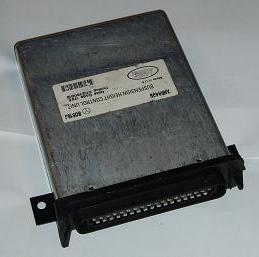
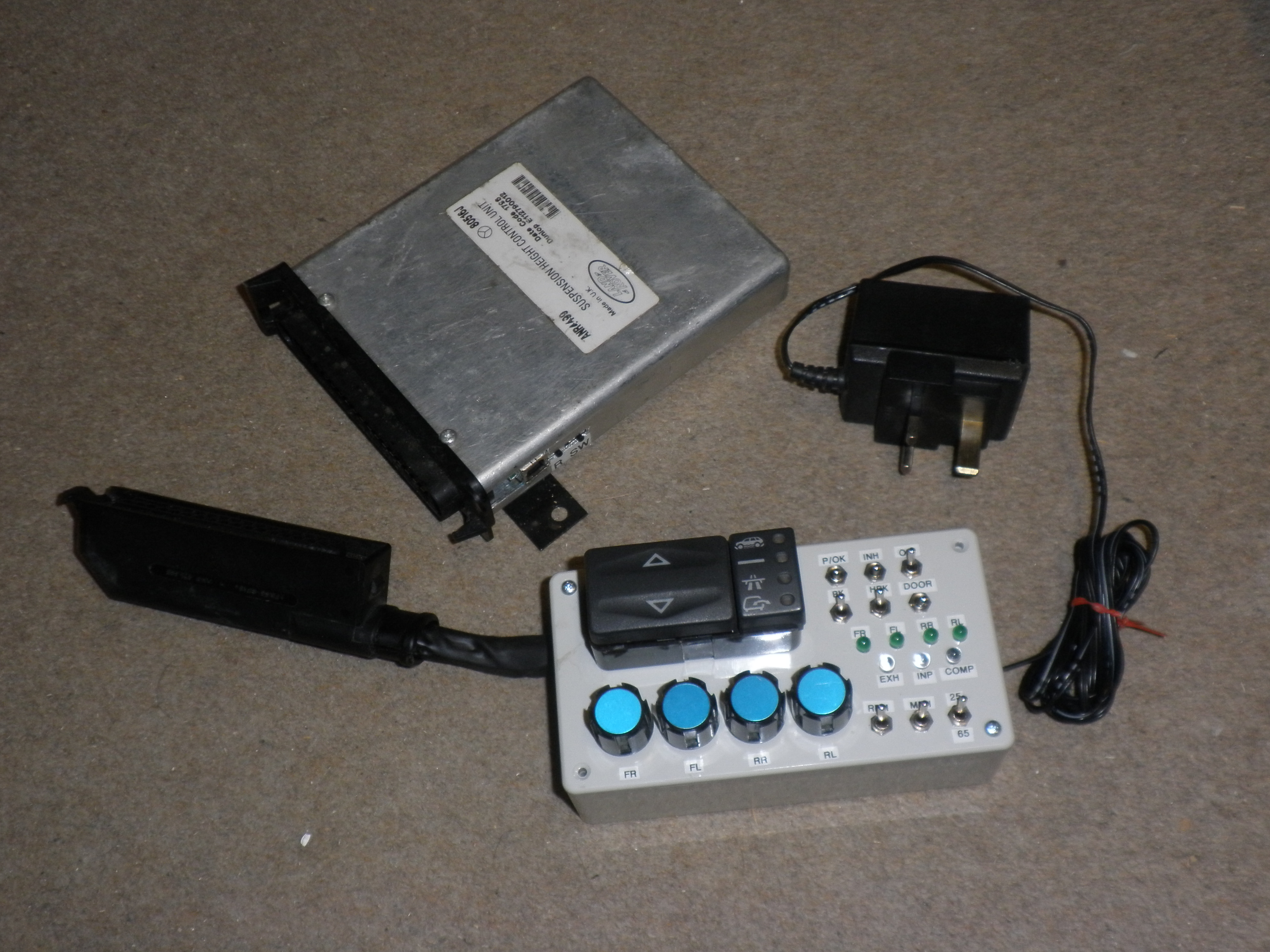
Step one was the purchase of a spare ANR4499 Suspension Height Control Unit via
EBay. It wasn't new and when I ran it in the car it worked for a while and then
did just the same this the other one did so I felt assured it wasn't the
computer directly, it was just the unhelpful software loaded into the thing.
Well I'm an Electronic Engineer specialising in embedded computer systems. This
is what I do for a living. I can fix this and I can fix it properly.
The case is pop-riveted together but that's hardly a problem. The first
disappointment was a CPU with the code inside and a part number that implied it
was a semi-custom system. OK so no quick reblow of an EPROM this time. This
is going to be open heart surgery. Run up the hot-air solder gun, yes I do have
full surface mount rework equipment at home, and out came the Central
Processor.
An assessment of the wiring diagrams for the car give me a feel for the number
and type of inputs and outputs in use so I selected a Arizona Microchip PIC
18F4550 CPU to replace things with. I like the Microchip kit and I have the
compilers to work on it so for a one-off it that an easy choice. This
particular chip has the added advantage that I can fit a USB interface and read
and write data and even reprogram the whole core with new microcode via the USB
line. This would mean that software tweaks could just be a matter of sitting in
the car with the lap-top plugged into it and getting the micro-code
just so.
The rest of the spec of the 18F4550 is 32K of program memory, 48MHz clock (the
original ran at 4MHz), 2K of internal RAM and 256 bytes of EEROM for all those
calibration constants and the all important error reports. A2D converters,
pulse rate capture ports, serial ports, timers and lots of I/O pins. There is a
430 page datasheet downloadable from the Arizona website if you want it and it
only costs about a fiver. I did wonder about using the surface mount version
since I wanted to do a PCB for reliability but decided that as I had a
programming jig in DIL for the Arizona range I might as well take the easy
route rather than the pretty one.
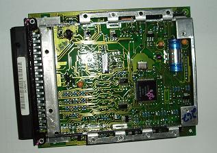
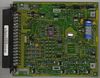
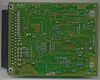
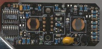
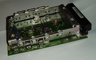
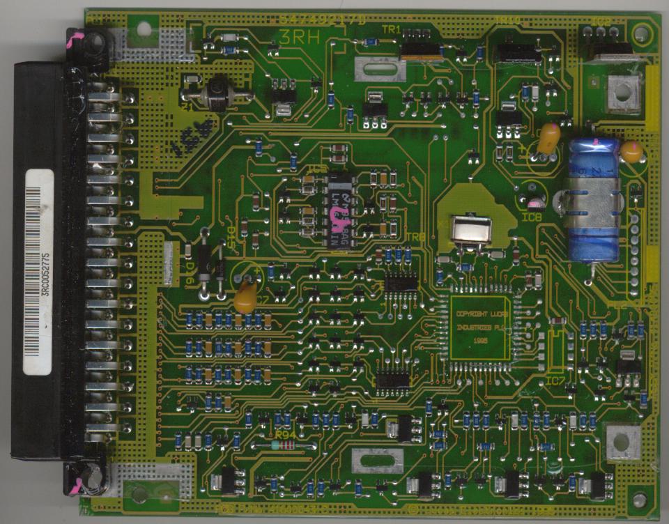
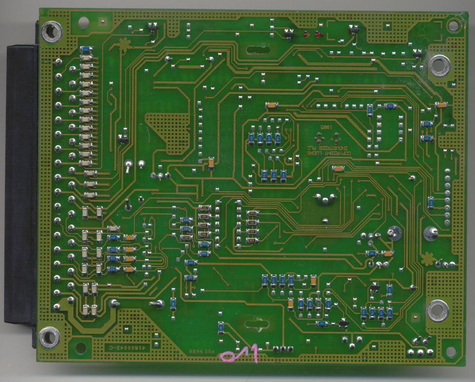
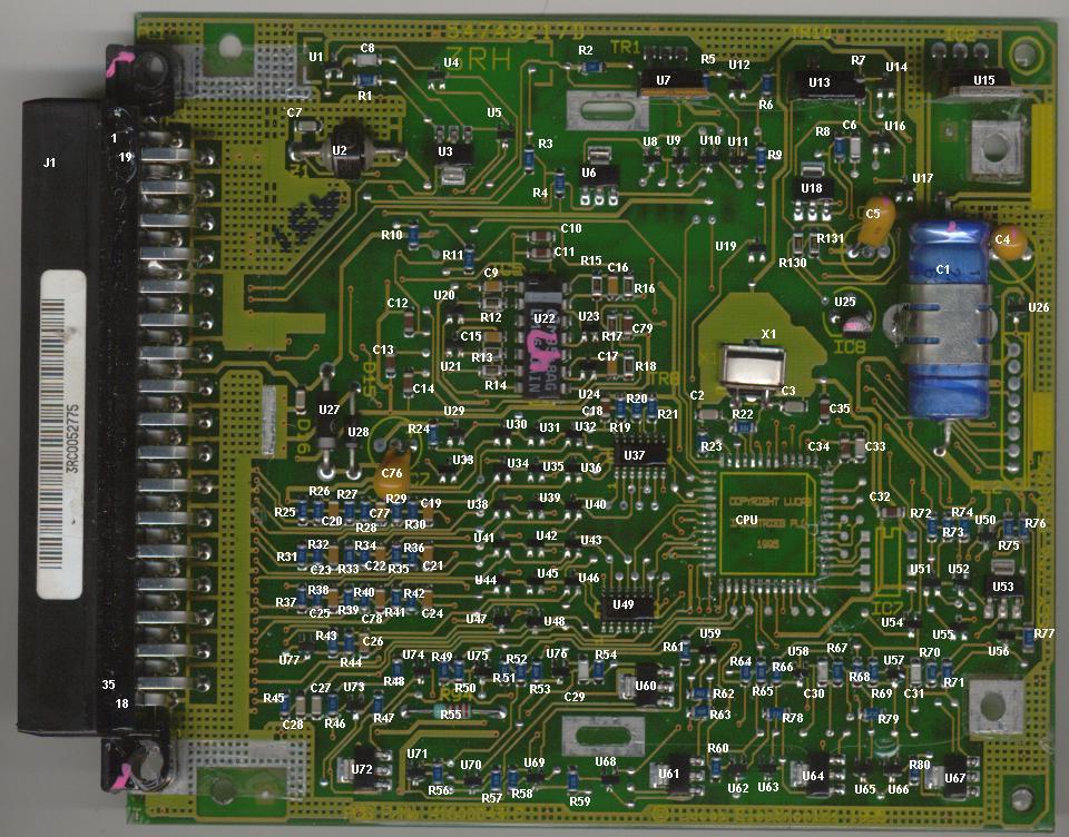
Ok here are the scans of the two sides of the PCB after I removed the metal
frame that acts as a heat-sink for the power devices.
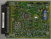
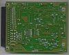
Top and Bottom and
here they are again with the component numbers I use in the following
discussion: Top and
Bottom. Please notice that these are my
component numbers and contradict the few that are marked. Also all the
semi-conductors are marked U something because in SMT it's hard to tell diodes
from transistors etc. At least with these diagrams I could work my way round
the PCB and try to understand what was going on.
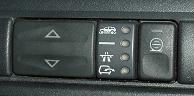
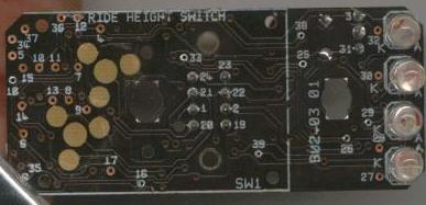 OK snag number one. The little Ride Height Selector Switch with the lights on
only has two wires for four lights so there is some encoding going on here.
Back to EBay and buy a switch for a couple of quid and destroy it.
OK snag number one. The little Ride Height Selector Switch with the lights on
only has two wires for four lights so there is some encoding going on here.
Back to EBay and buy a switch for a couple of quid and destroy it.
It has two ICs inside. One is a dual pulse generator and the other is an eight
bit shift register. At first sight it clocks in four data bits on a rising edge
and first bit in is the lowest LED and the final bit is the highest one.
Interestingly the highest LED, denoting Boulder Strewn Riverbed mode has
a wire back to the Body Electrical Control Module for some reason.
However, just because only 4 bits are used here does not force there to not be
more bits as the two wires, data and clock, are also connected to the BECM
directly. The BECM does not apparently drive the switch as with no power relay
in the switch lights come up randomly and never change.
One half of the pulse generator is used to delay the clock 120μS so both
data and clock can be set simultaneously and the data is given time to settle
before being sampled and the other half is used to prevent the display being
updated while the data is shifting so the lights don't flicker (a 37mS period).
A quick look at the system as it starts with the EAS unpowered shows it running
normally for about a second and then the error lights come on and the 35 mph
message displays. I'd guess the new lamp code is sent every half a second or so
and no message is interpreted as no EAS.
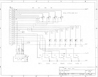
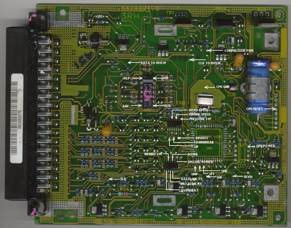
 OK. I won't bore you with the internal details of the circuit of the EAS ECU
mainly because I can't be bothered to redraw my scrappy sketches onto the cad
system but here is the pin out for the connector on the
ECU. I traced the circuitry and mapped the signals onto the PCB which gave
me the connection points by name. All the logic
signals are referenced down for a CPU running on 5 volts and the analogue
inputs are buffered and amplified similarly. Nothing is muxed. Nothing seems to
require special handling except the Ride Height Switch.
OK. I won't bore you with the internal details of the circuit of the EAS ECU
mainly because I can't be bothered to redraw my scrappy sketches onto the cad
system but here is the pin out for the connector on the
ECU. I traced the circuitry and mapped the signals onto the PCB which gave
me the connection points by name. All the logic
signals are referenced down for a CPU running on 5 volts and the analogue
inputs are buffered and amplified similarly. Nothing is muxed. Nothing seems to
require special handling except the Ride Height Switch.
 Right now this wants fitting to the 18F4550 CPU with the minimum of fuss.
The planned items were:
Make the In-Circuit programming work so I don't need the USB. This will
save me pulling the CPU out if I send something really silly down the wire.
Connect the engine and road speed signals to the Capture/Compare module as they
look like pulse trains.
Use the on chip analogue to digital converter as 10 bits gives us resolution to
thousandths of max range. Nobody needs to set the ride height to one tenth of a
millimetre so it must be enough.
Use the supplied USB reprogram module so keep the special switch for the
reprogramming mode and do not put anything on the 'lights' it flashes.
Do a full high speed USB connection.
Put the 'datalink' stuff to the 'test book' plug on the built in serial port
as, even if I'm not planning to connect anything to it, I might want too one
day and all the stuff I hear implies it is a serial port.
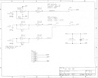
Here's my plan for a 40 pin DIL cpu and the circuit
diagram for the CPU board.
 Right so the next
problem is to reconstruct it so it can be reinstalled and maintained. In my
book this does not involve pop-rivets.
Right so the next
problem is to reconstruct it so it can be reinstalled and maintained. In my
book this does not involve pop-rivets.
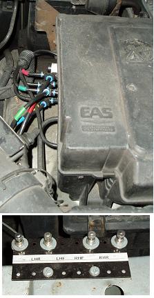
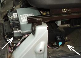
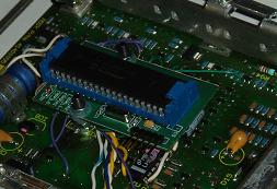
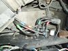
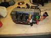
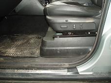
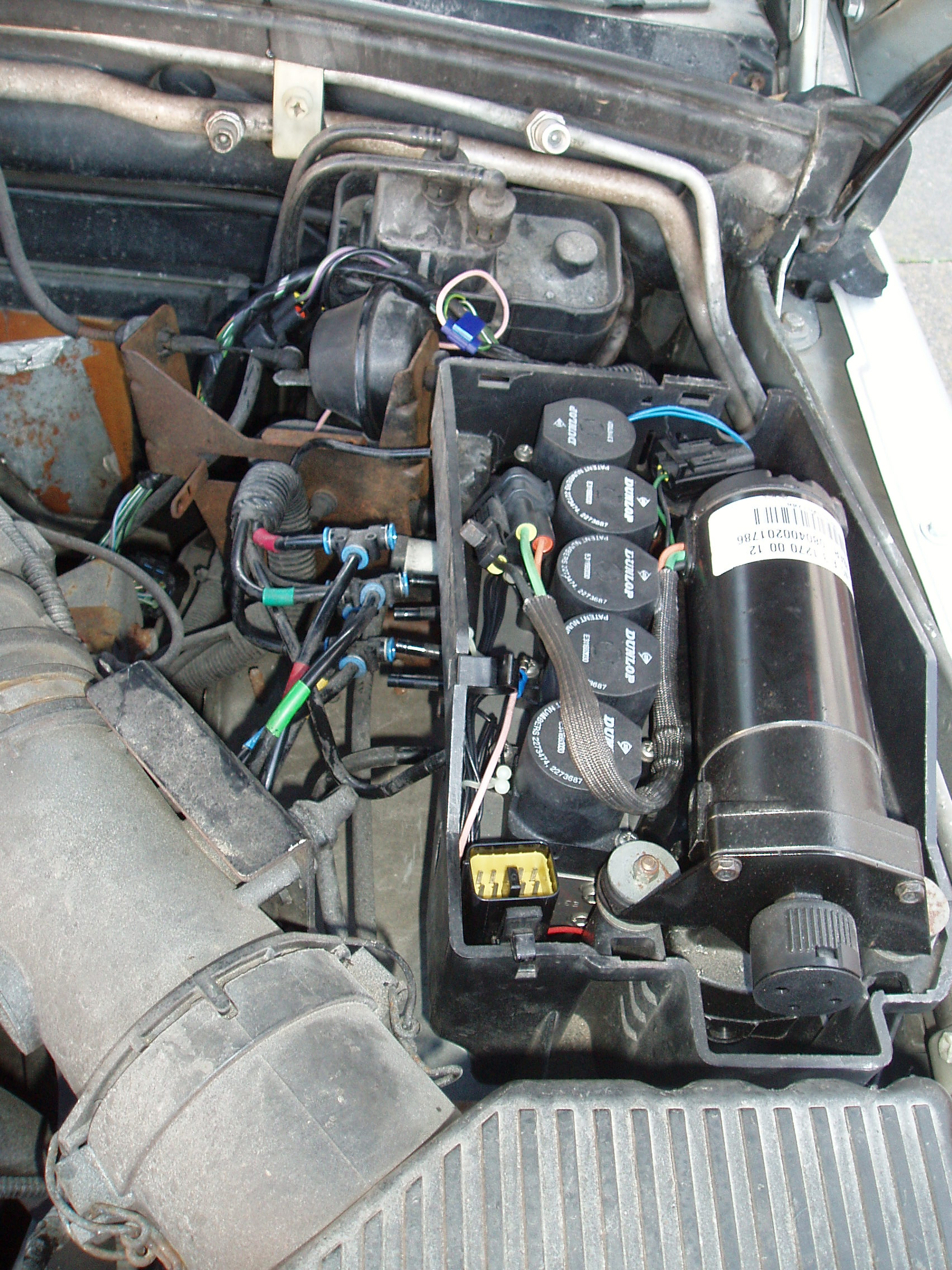
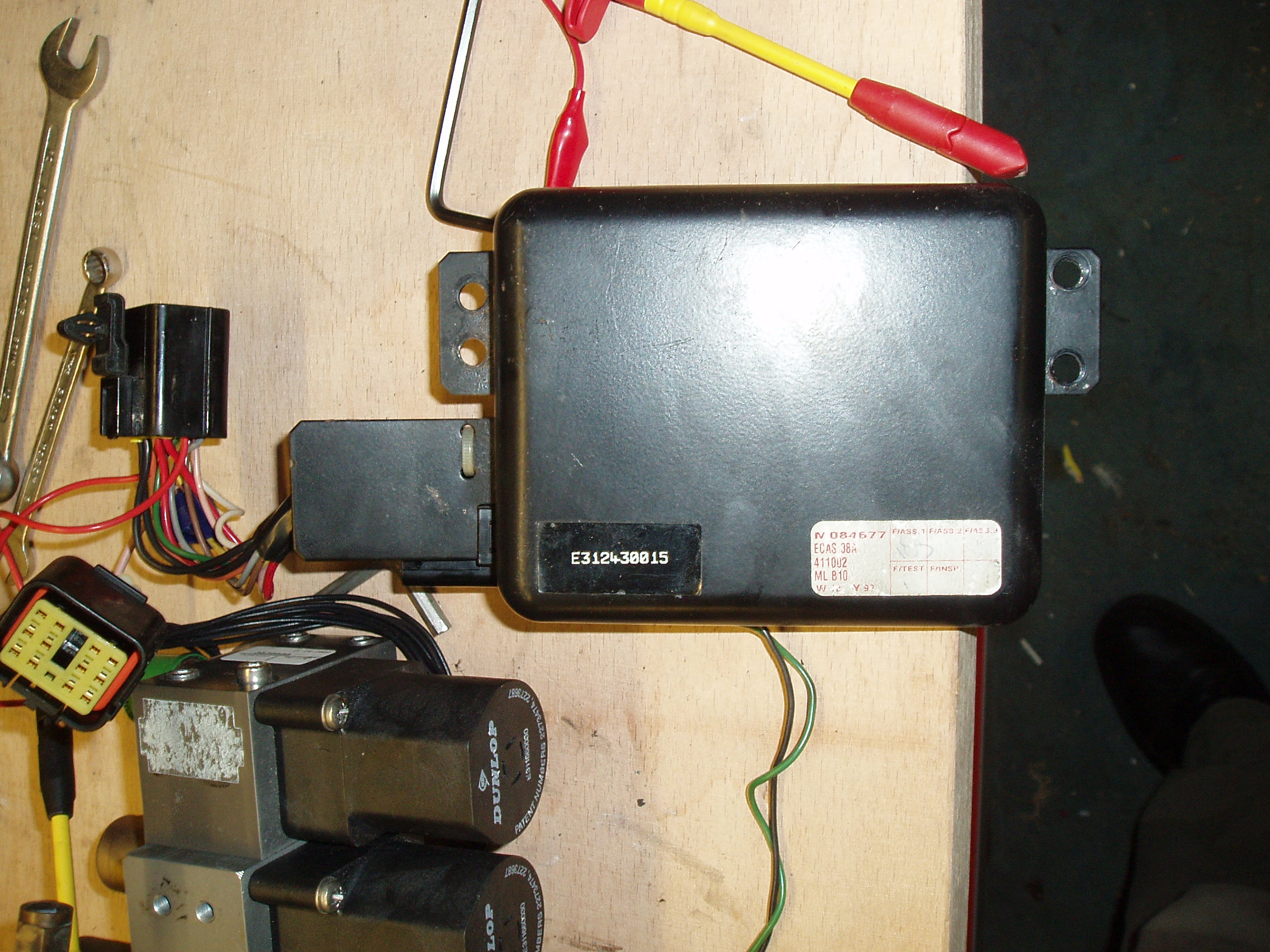
The picture shows the installed position under the passenger seat where the EAS
ECU is centre left underneath a gearbox ECU. In this view the Power Delay
relay (the thing that keeps it switched on so you can work the suspension for a
bit after turning off the ignition) would be in the socket with the blue blob
on it but this picture is the old ECU in messed up head mode so the relay was
out to keep some scuba air in the suspension.
The PCB is inverted when it is installed but putting a USB connector through
the side of the case near the front on the outside seemed a natural test,
diagnostic and reprogramming adaptation. Remember that there is still a fault
with my air suspension, one that drives the CPU mad, so when this is all
working I need sensible problem reports so I can fix that. Odds on a bad
connection somewhere anybody?
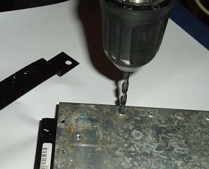
 First I trimmed the metalwork to get room for the USB connector. Sadly I can't
punch the USB socket into the PCB as I will never get the metalwork off again
so it will have another mounting method. Then the rivet holes were drilled out
and cinche nuts pressed in. M4 was perhaps a bit over generous here as in one
hole the drill carried away all the metal so I'm a bolt short of ideal but it's
not near anything that needs heat sinking an there were spare holes anyway so
it doesn't need the screw to damp-proof it.
First I trimmed the metalwork to get room for the USB connector. Sadly I can't
punch the USB socket into the PCB as I will never get the metalwork off again
so it will have another mounting method. Then the rivet holes were drilled out
and cinche nuts pressed in. M4 was perhaps a bit over generous here as in one
hole the drill carried away all the metal so I'm a bolt short of ideal but it's
not near anything that needs heat sinking an there were spare holes anyway so
it doesn't need the screw to damp-proof it.
The key trick is to make and mount the PCB so it will survive the kind of off
road experience that was one of the reasons for buying a Range Rover in the
first place. I located two points on the board that I feel I could safely drill
a hole and put a pillar into and drilled it 3mm. To fit a 2x3 inch PCB over
that are I only need 7mm of clearance. (Sorry I keep unit switching but PCBs
are still in my mind as designed on the one tenth of an inch grid as that's how
all our components come so we work in inches while our fastenings are all
metric. We dive mechanical engineers nuts.) The PCB wants to be of ground-plane
type construction as that makes for nice stable CPUs once you start clocking in
the tens of MHz and above region.
The total height I have to play with is 21mm so with 8mm spacing, 1mm for the
PCB thickness I still have 12mm before I bump the case. This means I can have
test connectors and indicators on the prototype board - not that there will
ever need to be another but, hey, I make production quantity product, I think
that way.
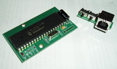 Right now, here are the new PCBs with the new CPU and the USB socket.
 I must be smug and say that Combro do do a nice PCB. The surface mount LEDs
are a nice touch. You can't see them? True. They are green and you don't see
them until they light up.
I must be smug and say that Combro do do a nice PCB. The surface mount LEDs
are a nice touch. You can't see them? True. They are green and you don't see
them until they light up.
The only snag is that although my brother is a wizz on the CAD system the other
brother in the partnership missed one critical dimension on the small board and
got a couple of net labels wrong on the other. Still once it was mounted the
ghastly botch with a hacksaw barely showed.
It needed a lot of work before it was ready to boogie though but standing on a
couple of M3 bolts it looks quite neat. I must confess it is less tidy
underneath. There are 32 wires connecting the new CPU card to the PCB beneath
and I started wiring in nice heat-proof hook-up wire but as the quantity
of cable grew I got nervous about how the board would ever fit with all that
underneath it so I shifted to some thinner stuff but with a slight tendency to
shrivel away from the soldering iron. However it's all done and I'd rather have
flexible cables in a car application.
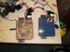
 I can't finish this section without a shot of it hooked up to the remains of
that ride-height switch I bought. OK the program I was running at the time was
just "read the switches" "write the lights" but it was nice to see something
working after all this time.
I can't finish this section without a shot of it hooked up to the remains of
that ride-height switch I bought. OK the program I was running at the time was
just "read the switches" "write the lights" but it was nice to see something
working after all this time.
Well this was the point where I thought it would all be plain sailing and the
software would be the easy bit. OK I'd had some problems with the programming
jig but when I discovered that the problem was pin loading adding a secondary
socket between the programmer and the chip with all the pins cut off except for
the ones I needed sorted that. There is something very funny about writing
to port A on these PICs but that is probably because I have it smeared over
the Analogue to Digital converter pins. Also it was a bit of a head banger
getting the USB going but there was more fun to come on that score.
Once I got over the elation of real lights changing to button presses I noticed
that when I pulled out the USB cable everything stopped. This was worrying as
permanently plugging in the lap top when I want to drive was not in the game
plan. However I started to dig.
A quick poke with the 'scope showed the oscillator stopping as the cable came
out and, since it picked up again from where it left off when you put the cable
back, that had to be 'SLEEP' mode. A delve into the standard library from the
chip maker showed it just happened to have helpful code to kill the CPU into
power-saving mode when you pulled out the cable. A quick mod to the library and
the oscillator kept running.... pity nothing else did. Now digging into the
other parts of the library turned up code that loops to give the USB system the
benefit of the whole CPU when it is in disconnected mode. Another library frig,
and this one has to be a bit more wary as this code overlaps projects we are
selling, so no bugs here. Finally the lights flash and move without the
USB.
OK so it's 9.30 at night and wet as can be but this is going in the car with
null software to see if it drives the switch there AND does it get rid of the
SLOW:35 MPH MAX message? To cut a long story
short it does. It did flash a 20MPH MAX message at me a couple of times but
mostly everything was OK. Nothing turned on, so I have all the right
initialisation values, and the dimly remembered RANGE and MPG displays showed
up. Went to bed a happy bunny.
The next couple of days involved sorting out the Analogue to Digital
converters, discovering that the 'Engine RPM' signal was, as suspected, spark
rate so an easy conversion, checking the outputs really did output and
improving the program that ran on the PC to keep track of all the data I could
generate. With that done real numbers were being obtained so I was ready to
move. forwards to actually controlling something.
The first trials worked but weren't all that exciting but I now had suspension
again.
The next CPU problem was the Microchip boot-loader. The problem was that it is
designed to flash lights to tell the programmer what his program is doing but
just to reassure the rest of us that things are working. However the two lines
it wants to use are two of my solenoids and I don't want to flash them.
Originally I though I could just disconnect while program loading and I had
arranged for the CPU to power from the USB to make this happen but this was
beginning to get tiresome. The answer was to identify the program instructions
that drive the lights from the supplied listing and hit them with a binary
editor to NOPs...
So if anybody else needs a Microchip variant bootloader tested on a 18F4550
that does not even initialise the PORTE LED bits here it is
nig-boot.hex.
It still obeys PORTB bit 5 low to go into boot mode but to change that would be
a one location hit.
Now at least I just need to push one button while holding the other down and
I'm in program load mode.
 More on the Ride Height Switch lights
I got the 'scope on the system
and made a basic analysis of what was coming out and, since I had already
dissected a switch, the protocol was simpler than I expected. The plot shows a
normal display of the third light up lit. Click the thumbnail for a
readable image.
The clock line, the blue trace, stays high (12V) most of the time but since the
board inverts both signals that is a logic '0' out from my CPU. It goes low for
2mS and is then high for 8mS between pulses. The pattern repeats every 100mS.
The data line (blue trace) is clocked into the switch's display shift register
by the rising edge of the clock so if it is required to be low it sets low with
the clock and sets high again 2mS after the clock. Between the 100mS frames the
data line alternates between high and low and this probably supplies a
simplistic I am alive signal to the BECM without the CPU there having to
actually read the data. If you look at the plot you can see the rising edges of
the blue line match up with the red being low, low, high, low in both cases.
This sets the lights in ascending order. This is reasonably trivial to program.
I have a 1mS heart-beat as my basic timer so I will just service the data lines
every 2mS and cycle in 200mS to cater for the alternating state of data in the
gap.
I started to cut the picture of my simulation but realised that was silly. You
can't tell them apart. The only snag with testing indoors is that you need to
add pull up resistors to the test jig, I used 5K6 to 12V, because the EAS ECU
only pulls down.
Incidentally... If I set the line high in both gaps rather than alternating the
BeCM displayed the 35MPH warning message and if I set it
low it showed EAS Manual.
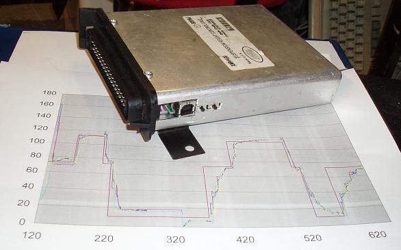 The first version ran
reasonably. The plot is a test run - time in seconds and height in mm. It was a
bit slow but it followed the demanded height quite well.
The first version ran
reasonably. The plot is a test run - time in seconds and height in mm. It was a
bit slow but it followed the demanded height quite well.
It didn't do things like always lift the back first yet as it just trimmed
round to taper into the required height and it was having trouble talking to
the BeCM even though the ride-height switch on the same circuit was quite happy
as this was before I got my ECU reset and 'scoped its outputs (see above). It
did, however, allow me to dump out values and begin to see a pattern where it
would drive high. Remember I am still hunting for the elusive fault that drives
EAS ECUs mad and I begin to suspect a wiring problem in the sensors.
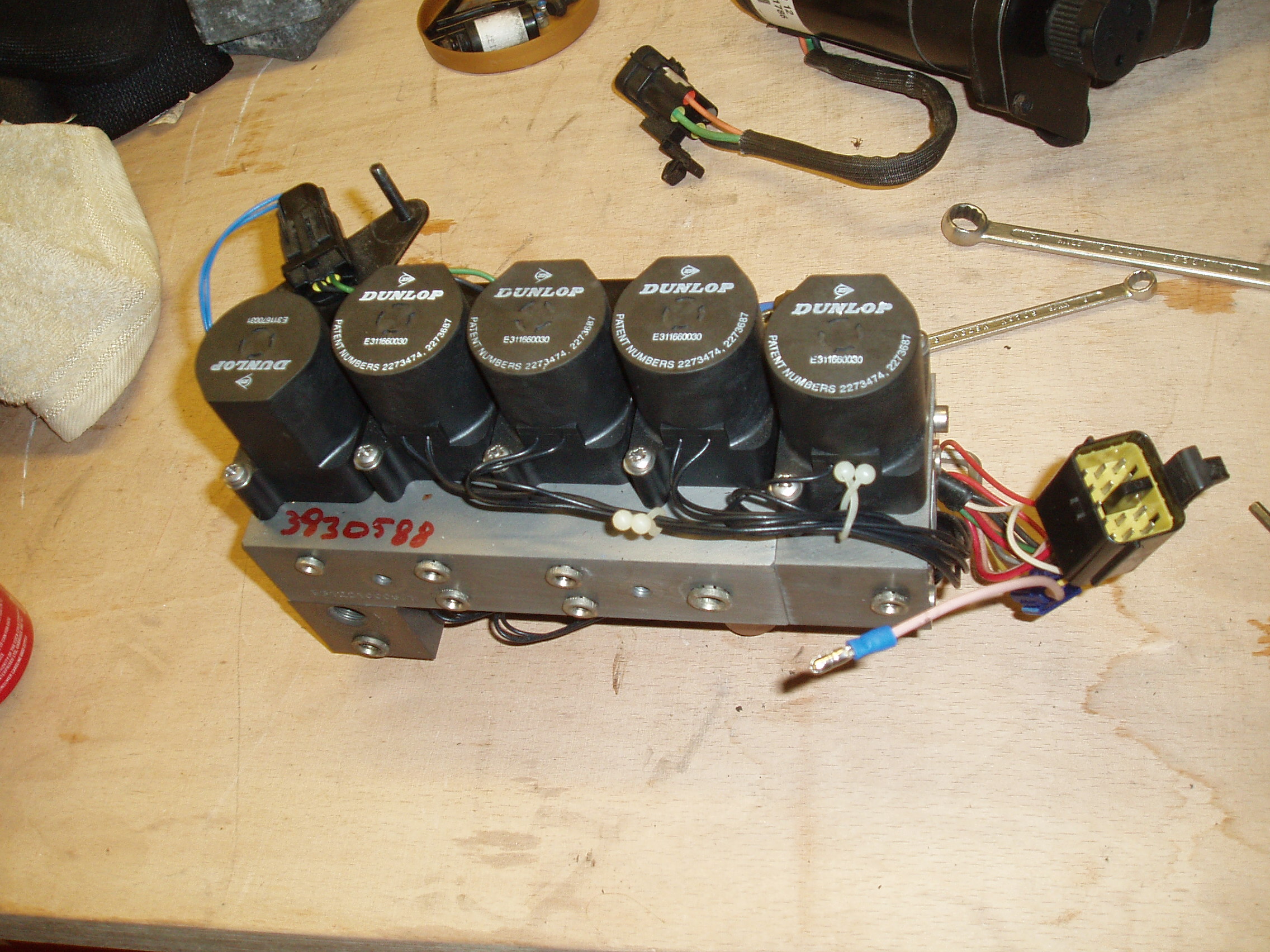
Revise that: a wiring problem to the rear-right solenoid. It was now pretty
predictable. The rear-right wheel didn't respond. That is a killer to the
standard box but not to mine. Rattle the cables on plug C152 and most times it
comes back. Now the valve gear has been changed twice so the plug itself is
worth looking at. So I put it into the shop for a new plug, specifically a nice
new set of crimps. Watch this space - as they say...
Well that didn't seem to fix it but it's still intermittent and rattling the
cables on C152 makes it come and go. I was frustrated and just put up with it
for a while. What-ever the problem was it now failed first thing but once the
whole system had warmed up it worked so it wasn't too bad now I had a box that
didn't need resetting all the time.
So what next? I tried
putting a bridge wire from the harness to bypass the whole C152 section but
that worked for a few weeks then the fault came back. It does seem that
disturbing the wiring improves things which, I suppose, is why the garage can
always 'fix' it. It just doesn't stay fixed and I really want it to stay
fixed.
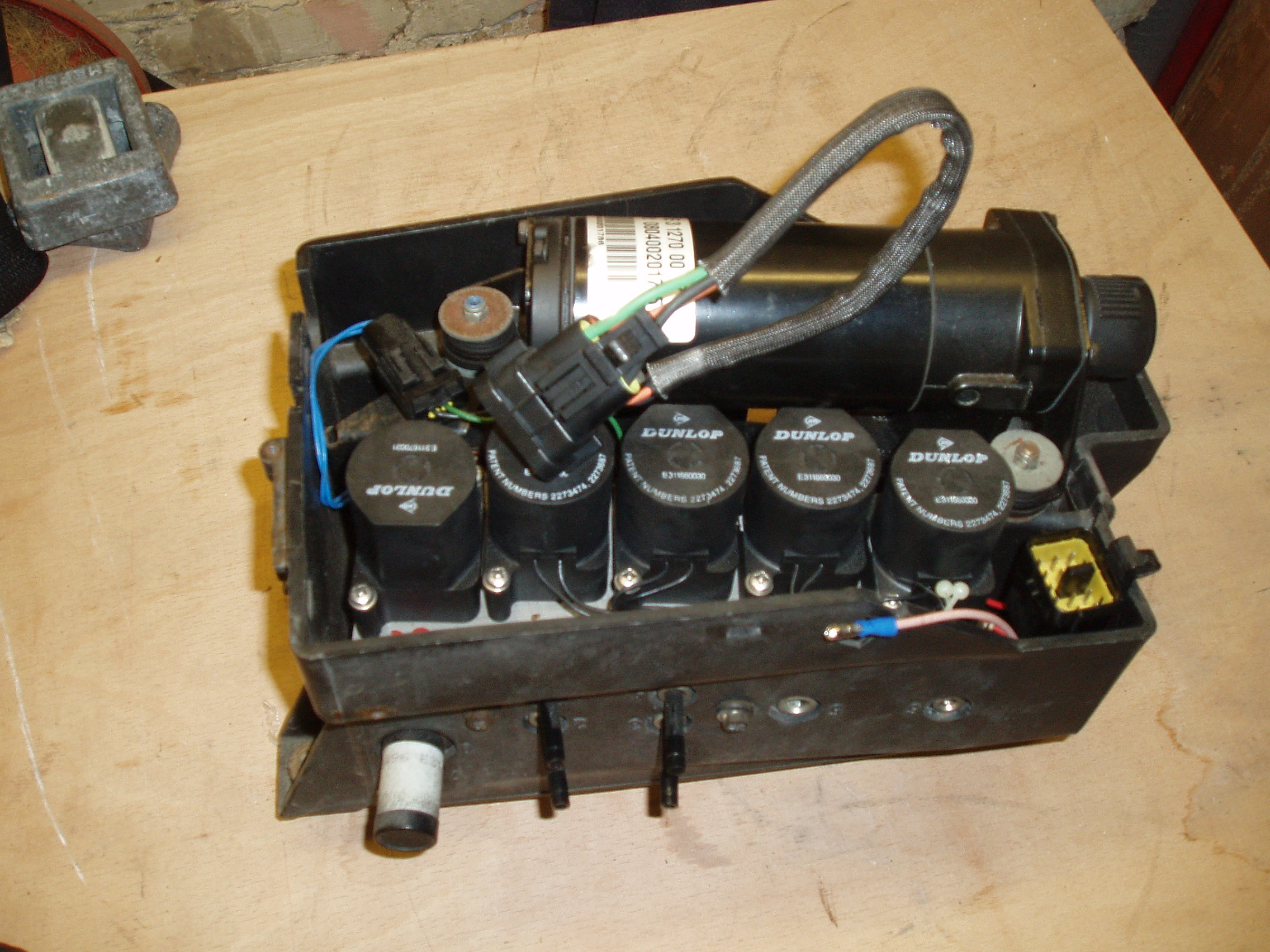
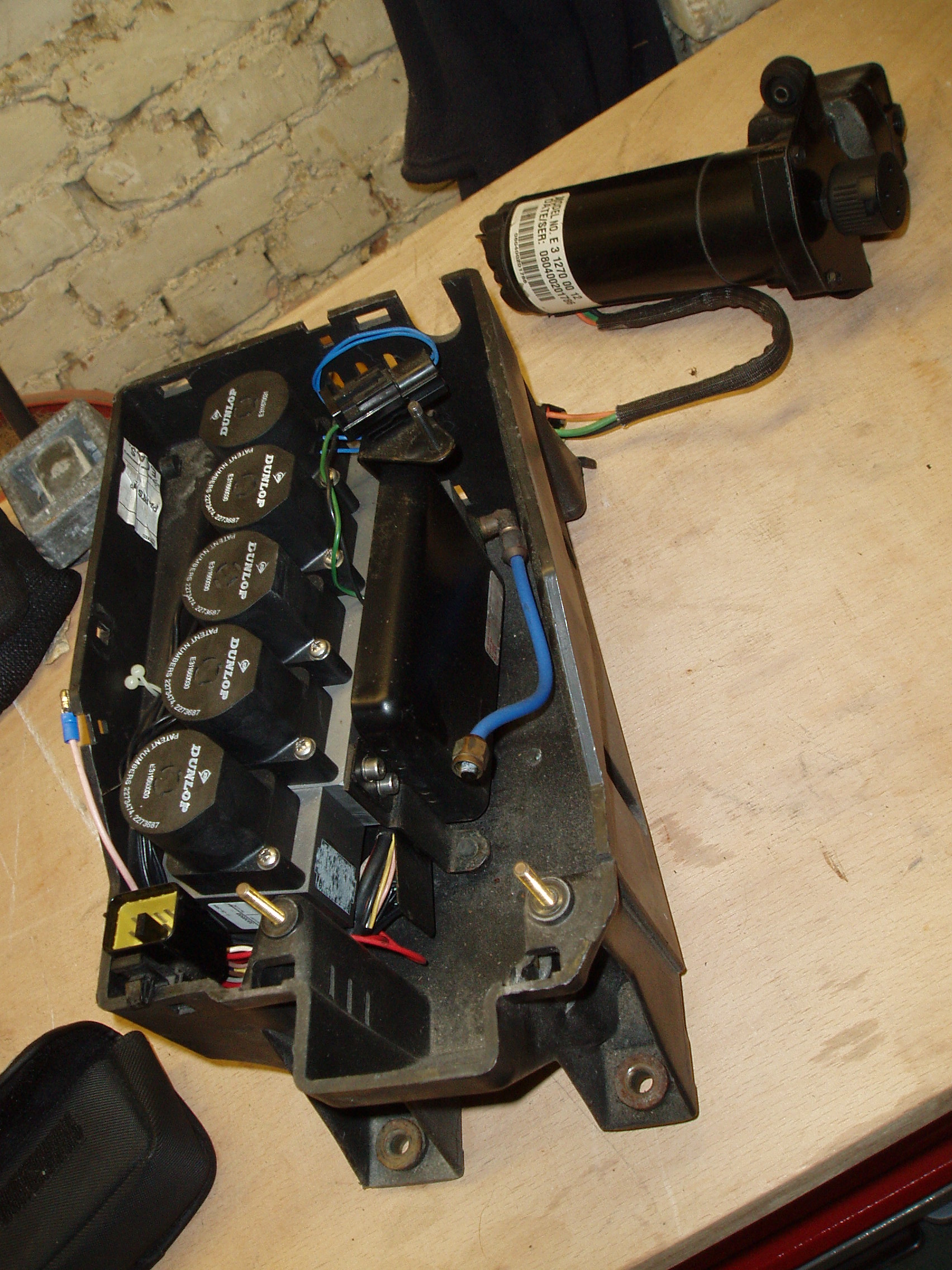
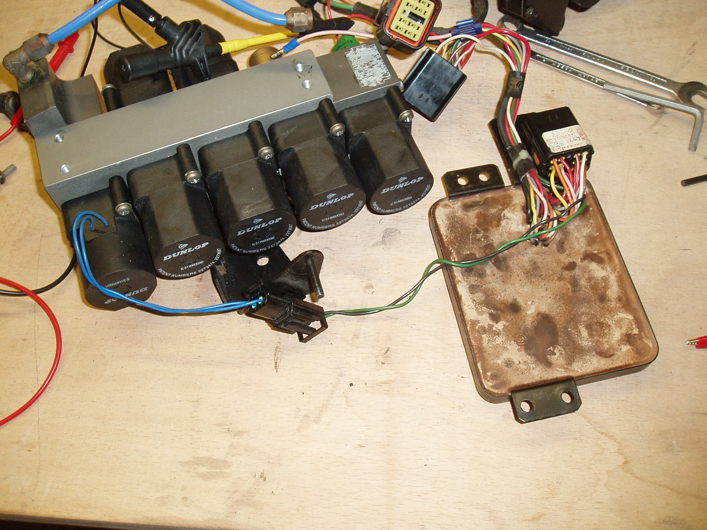
So I delved again with a voltmeter on the wire and jiggling things about. The
connection seemed good and yet the valve was not pulling in so it was time to
take the whole box apart, something I'd rather been putting of until then. I
got out the camera again so I had a record of how it was to go back together
again (they are big files so don't bother unless you really need them).
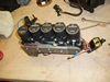
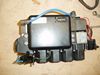
Sadly, by the time I've got it on the bench the intermittent fault is not showing
but I am somewhat surprised to discover that the valve block may be dated 2004
but the electronics package is dated 1984 and, frankly, looks it. I wiggle the
wires and I think I got a momentary break on the right one but it's impossible
to be sure but I decided to change it anyway. I Googled the part number and
www.p38spares.co.uk came up and they had one in stock at £170 so I
ordered it and fitted it.
 So what happened? I wasn't sure at first but it seemed to be working and after
most of a holiday away I swapped back onto the original computer to see if it
would stay going. Well so far it has.
So what happened? I wasn't sure at first but it seemed to be working and after
most of a holiday away I swapped back onto the original computer to see if it
would stay going. Well so far it has.
If it does turn out to be this I will be annoyed. The garage have removed this
lump twice to fit a new valve block. If you're going to do an expensive job and
then redo under warrantee it some checks might have been in order. I don't
know. I expect there are lots of good excuses but it doesn't do much for my
opinion of garage men. Like the twerp who has been cutting back and refitting
the perished end of my cruse control vacuum pipe for it to only last a
fortnight before it goes again. It may yet fail but it's still going a month or
more later and lots of miles. I'm taking it down to Geneva and back soon so it
it does that without a tremble I'm going to count it as a done job.
After another four weeks I refitted the cover on the boxes under the passenger
seat. How's that for confidence?
So what else?
Well things all trundled along for a while with the usual EAS grumbles but then
it started developing a 'leaky bag' symptom. So I sigh a big sigh and bung it
in the shop for a fix.
Well they fixed the worn front disks. They fixed the corroded rear brake pipes.
They fixed the worn anti-roll bar rubbers but, despite having it for three days
all they could say was that they couldn't get their computer to talk to the EAS
computer. By now the bill was getting into 4 digits so I brought it home and
promised myself I'd fix it.
 The problem was that I didn't really have 'nice' control of the system with my
current system. The on-board program had only been developed as far as it
needed to go to keep things running. I wanted a proper 'car simulation' to plug
it into at my desk so I could do the job simply.
The problem was that I didn't really have 'nice' control of the system with my
current system. The on-board program had only been developed as far as it
needed to go to keep things running. I wanted a proper 'car simulation' to plug
it into at my desk so I could do the job simply.
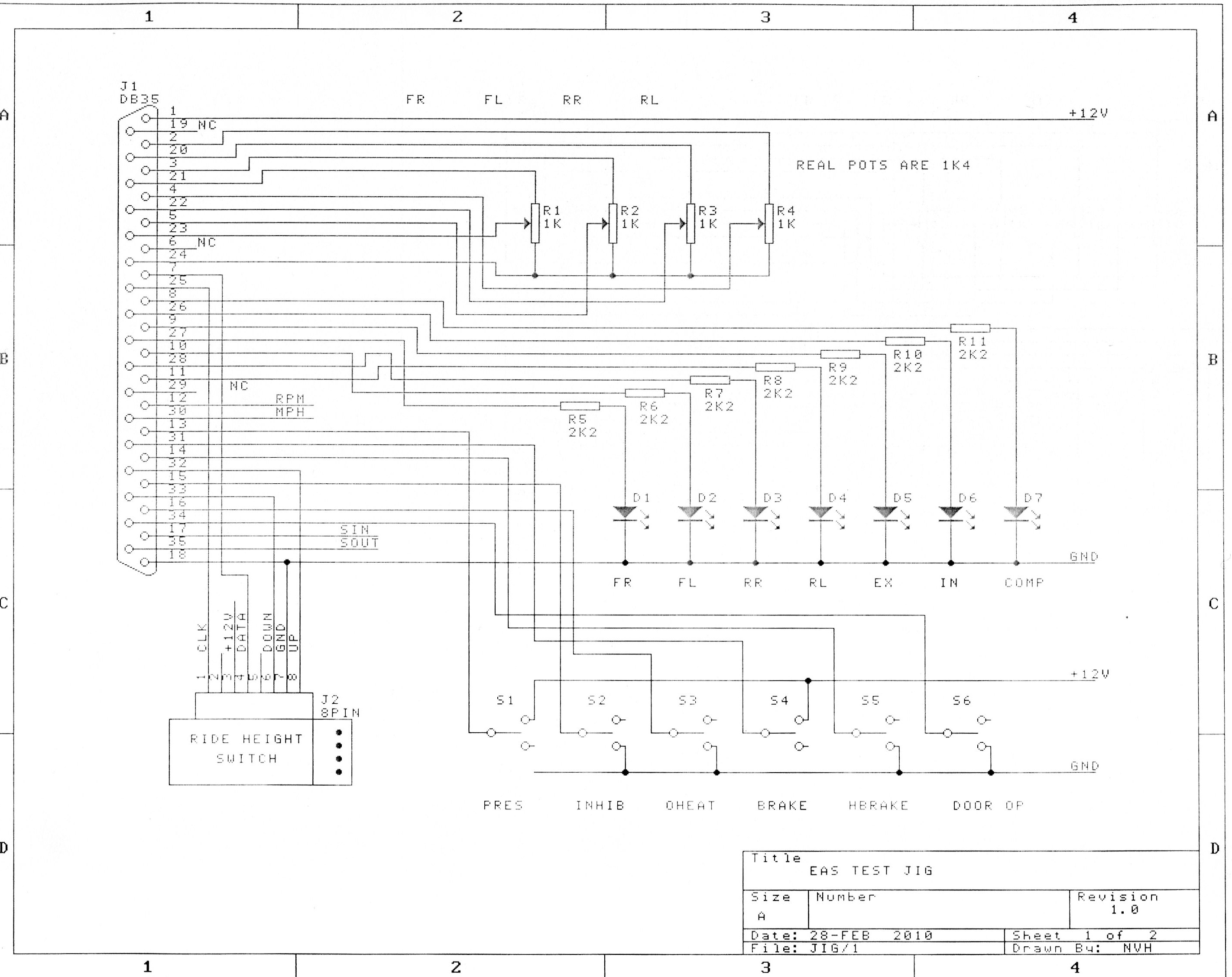
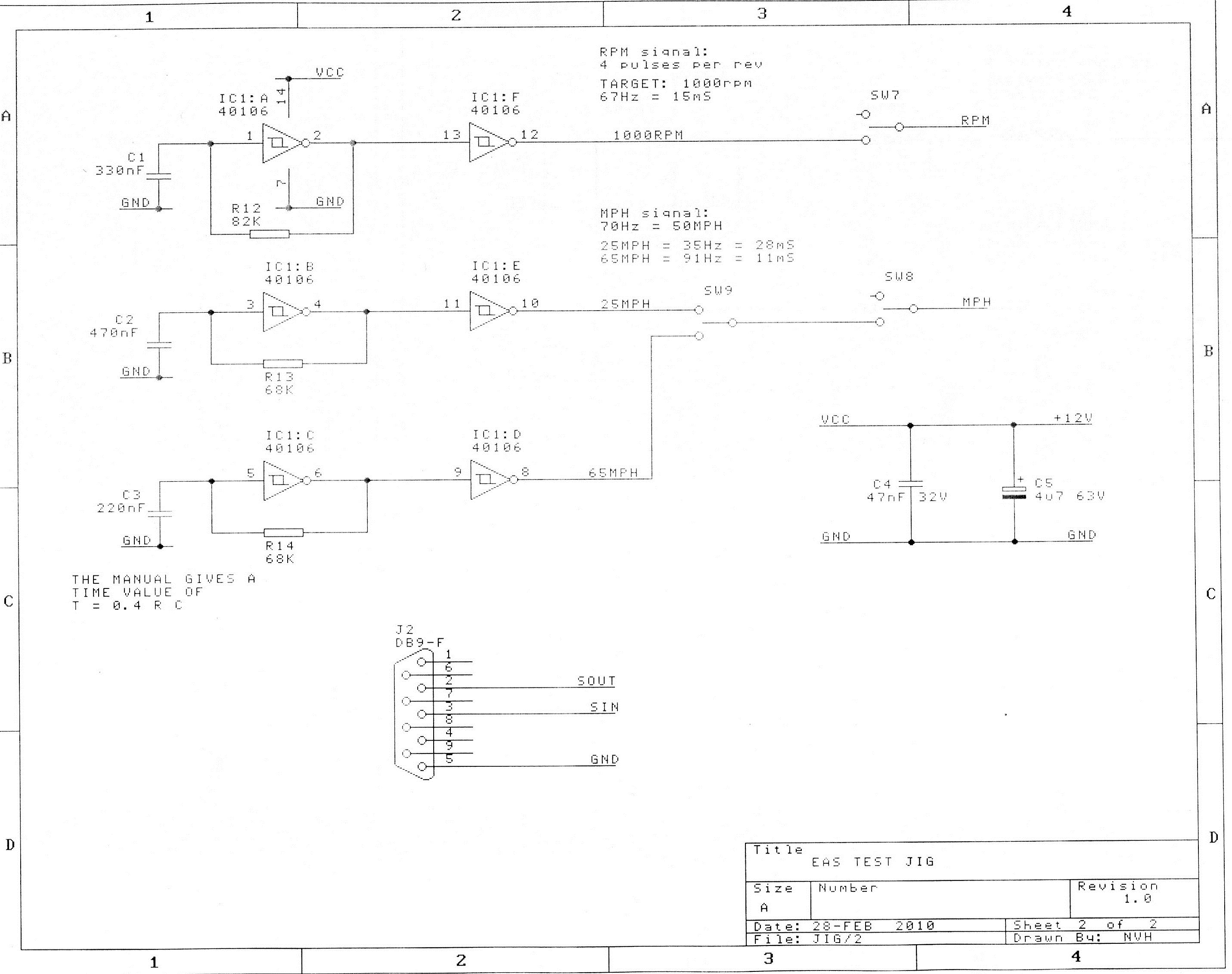
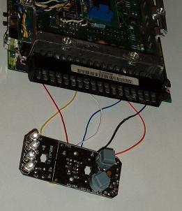
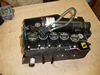
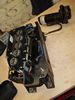
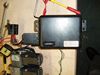
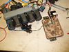
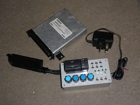
 So, out came the soldering iron and this is what I made.
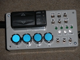
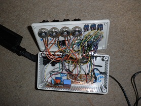
I used a real up/down controller from Ebay to 'prove' it worked but the rest of
the switched inputs are simple switches, the outputs are LEDs, the strut
variable resistors are normal 'volume control' style components with knobs and
the MPH and RPM pulse trains are generated by small oscilators. The engine
speed is a simple on/off while the road speed has an off state and two speeds
so I can see the ride hight change. The whole thing is powered by a 12 volt
power supply out of the junk box that used to power some gadget years
ago.
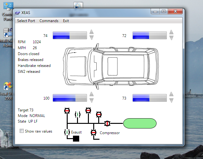
 Since my EAS box is USB controlled I also took the opportunity to upgrade the
original simplistic software so something that would give me more intuitive
control. It is written in WPF and is seen here running on Windows 7. I managed
to catch it with the screen grab when it reports the 'exhaust' and 'rear right'
valves open. If the 'Inhibit' switch is closed (ie the push button on the
Rangie dashboard next to the Up/Down selector the controller shuts all the
valves and waits for instructions. Clicking a valve toggles it between open and
closed while click-and-hold on the big up/down arrows next to the blue strut
height graphics open both the strut valve and the appropriate exhaust or
inlet valve and releasing the mouse closes them both again.
Since my EAS box is USB controlled I also took the opportunity to upgrade the
original simplistic software so something that would give me more intuitive
control. It is written in WPF and is seen here running on Windows 7. I managed
to catch it with the screen grab when it reports the 'exhaust' and 'rear right'
valves open. If the 'Inhibit' switch is closed (ie the push button on the
Rangie dashboard next to the Up/Down selector the controller shuts all the
valves and waits for instructions. Clicking a valve toggles it between open and
closed while click-and-hold on the big up/down arrows next to the blue strut
height graphics open both the strut valve and the appropriate exhaust or
inlet valve and releasing the mouse closes them both again.
AND FINALLY...
People keep asking for the source code and I usually warn them that the device
was never finished beyond the point where it allowed me to diagnose the problem
with the 'real' system so it won't be much use to them. However the the
requests keep coming so so I release it.
Usual GNU terms apply. This is UNSUPPORTED code that I wrote quite a long time
ago now and I am NOT answering questions on it because I don't remember any
details. It doesn't work well because it was only ever just a test
framework.
CPU code using the FED compiler (which I would NOT recomend)
XEAS Windows display module for VS2008
One last note: in 2017 the poor thing threw its MOT test like a ton of bricks
with a list of advisories to make you weep. It also had a bunch of other faults
I was 'saving' for after the MOT and when several required parts came up 'no
longer available' it just had to go the way of all things that have become more
expensive than their value. It went to a farm and probably was cannibalised to
keep two of its fellows working but I like to think of them sitting in a barn,
chatting about the good times. It was frustrating at times but fun. Rust in
peace.

 by Nigel Hewitt

 OK. I won't bore you with the internal details of the circuit of the EAS ECU
mainly because I can't be bothered to redraw my scrappy sketches onto the cad
system but here is the pin out for the connector on the
ECU. I traced the circuitry and mapped the signals onto the PCB which gave
me the connection points by name. All the logic
signals are referenced down for a CPU running on 5 volts and the analogue
inputs are buffered and amplified similarly. Nothing is muxed. Nothing seems to
require special handling except the Ride Height Switch.
OK. I won't bore you with the internal details of the circuit of the EAS ECU
mainly because I can't be bothered to redraw my scrappy sketches onto the cad
system but here is the pin out for the connector on the
ECU. I traced the circuitry and mapped the signals onto the PCB which gave
me the connection points by name. All the logic
signals are referenced down for a CPU running on 5 volts and the analogue
inputs are buffered and amplified similarly. Nothing is muxed. Nothing seems to
require special handling except the Ride Height Switch.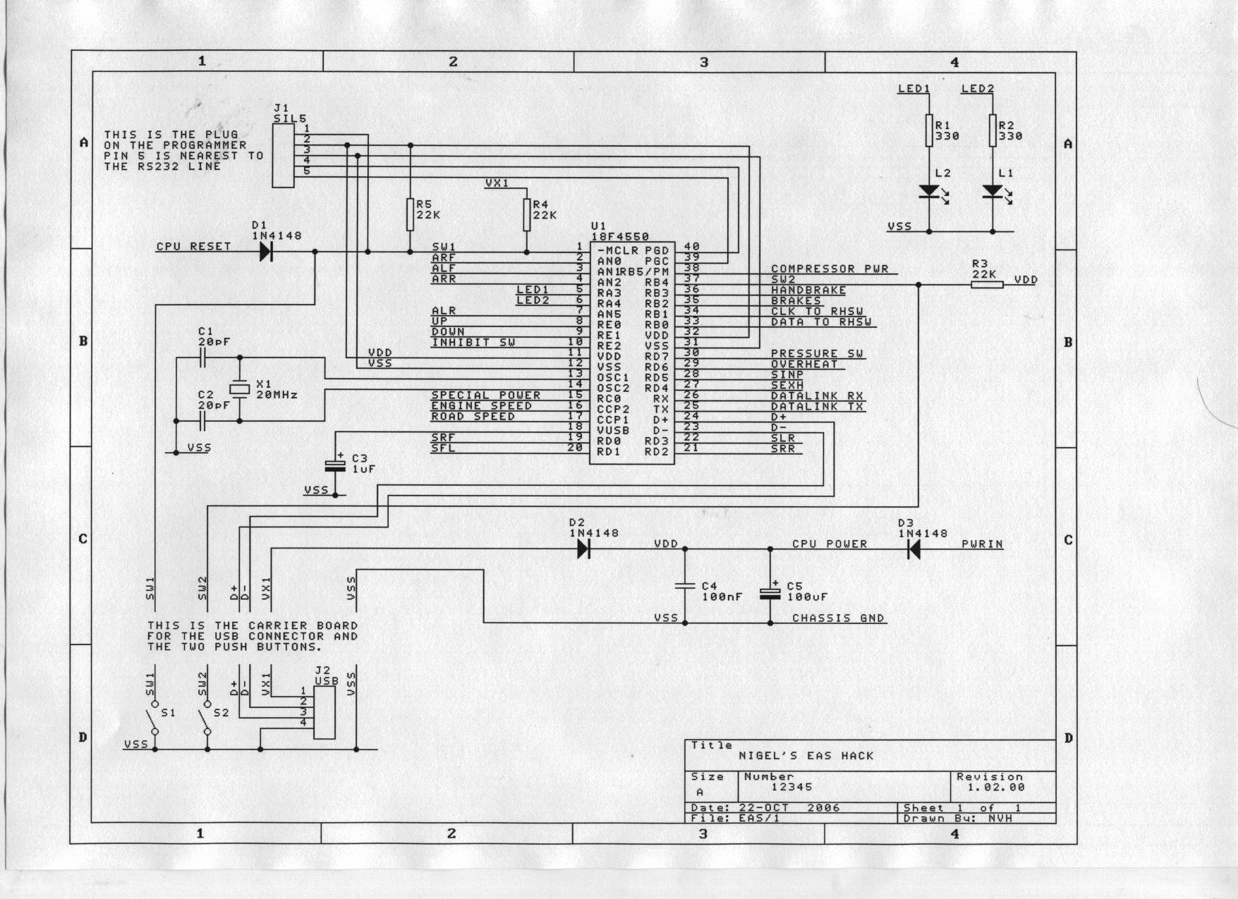 Right now this wants fitting to the 18F4550 CPU with the minimum of fuss.
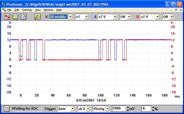 More on the Ride Height Switch lights


 The problem was that I didn't really have 'nice' control of the system with my
current system. The on-board program had only been developed as far as it
needed to go to keep things running. I wanted a proper 'car simulation' to plug
it into at my desk so I could do the job simply.
The problem was that I didn't really have 'nice' control of the system with my
current system. The on-board program had only been developed as far as it
needed to go to keep things running. I wanted a proper 'car simulation' to plug
it into at my desk so I could do the job simply.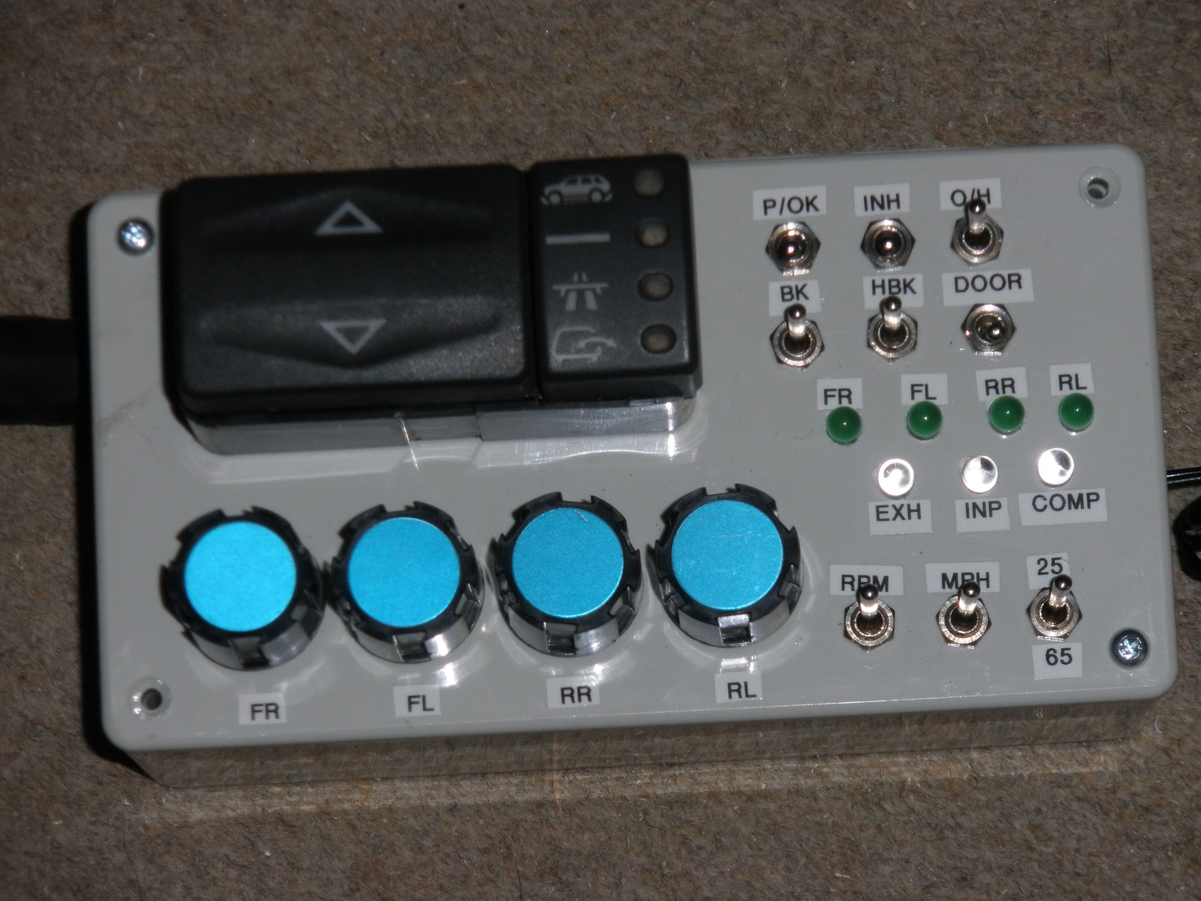 Since my EAS box is USB controlled I also took the opportunity to upgrade the
original simplistic software so something that would give me more intuitive
control. It is written in WPF and is seen here running on Windows 7. I managed
to catch it with the screen grab when it reports the 'exhaust' and 'rear right'
valves open. If the 'Inhibit' switch is closed (ie the push button on the
Rangie dashboard next to the Up/Down selector the controller shuts all the
valves and waits for instructions. Clicking a valve toggles it between open and
closed while click-and-hold on the big up/down arrows next to the blue strut
height graphics open both the strut valve and the appropriate exhaust or
inlet valve and releasing the mouse closes them both again.
Since my EAS box is USB controlled I also took the opportunity to upgrade the
original simplistic software so something that would give me more intuitive
control. It is written in WPF and is seen here running on Windows 7. I managed
to catch it with the screen grab when it reports the 'exhaust' and 'rear right'
valves open. If the 'Inhibit' switch is closed (ie the push button on the
Rangie dashboard next to the Up/Down selector the controller shuts all the
valves and waits for instructions. Clicking a valve toggles it between open and
closed while click-and-hold on the big up/down arrows next to the blue strut
height graphics open both the strut valve and the appropriate exhaust or
inlet valve and releasing the mouse closes them both again.